
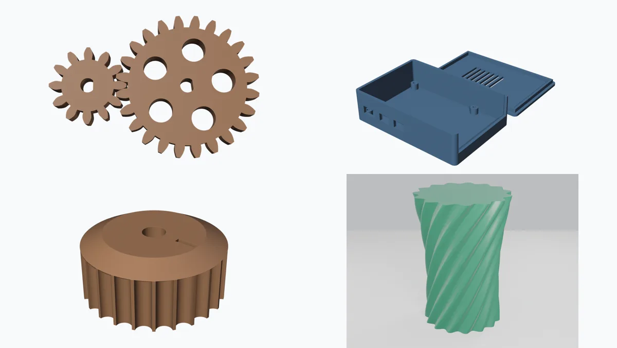
Three things called a “3D model”
Most confusion about AI and 3D printing comes from treating these as the same thing.
| Kind | What it is | Good for |
|---|---|---|
| Mesh | A skin of triangles. It has no idea what a hole or a 2 mm wall is. | Sculpture, figures, scans, film and games. The STL file a printer takes. |
| Solid | Exact geometry: true cylinders, flat faces, edges. Swapped between CAD programs as STEP files. | Engineering parts. |
| Parametric | A solid plus the recipe: “40 mm wide, hole 5 mm from the edge”. Change a number and the part rebuilds. | Anything you will resize, adjust or reprint. |
Where the AI fits
1. AI-generated meshes: impressive, but they don't fit anything
Text-to-3D and image-to-3D services (Meshy, Tripo, Hunyuan3D, Rodin and others) turn a sentence or a photo into a mesh in under a minute. For a figurine, a cake topper or a gaming miniature they are genuinely good. For a part they are the wrong tool: sizes are a guess, there are no real holes or flat datum faces, and the mesh often needs repair before it will slice.
2. AI-written CAD: the route that works for parts
Programs like OpenSCAD and CadQuery describe a model as a short text file: “a box 60 by 40 by 25, minus a cylinder here”. Text is what large language models are best at. So you describe the part, the AI writes the script, and the CAD kernel builds an exact solid from it. Every size is a named number at the top of the file that you can read, check and change.
# the first lines of the gear script in part 2
MODULE = 2.0
TEETH_A, TEETH_B = 12, 24
PRESSURE_ANGLE = 20.0
THICKNESS = 8.0
SHAFT = 5.0
CLEARANCE = 0.2          # added to the bore so it slides on the shaft
Because the output is a real solid, the script can also check itself. The gear script prints the centre distance and the volume where the two gears overlap. If that number isn't zero, the teeth collide.
3. AI driving the program
With an MCP connection (a plug that lets the AI operate an application), Claude can drive Blender directly: build a scene, set materials, render, check a mesh for holes, export. That's the subject of part 3. It's best for looks: organic shapes, product shots and mesh repair.
The one-line version for makers: the AI doesn't carve the part. It writes the instructions, like a cutting list or a CNC program, and the CAD software follows them exactly. You still check the numbers, the same way you'd check a drawing from a new apprentice.
What the AI is good and bad at
| Good at | Not good at |
|---|---|
| Turning a clear brief into a working script in minutes | Knowing the real size of your object. Measure it. |
| Fiddly geometry: involute gear teeth, hex nut traps, vent patterns, polar arrays | Knowing your printer's actual tolerances. Print a test. |
| Rules of thumb: 45° overhangs, 0.2 mm sliding clearance, wall thickness | Judging whether a part is strong enough for a load that matters |
| Changing a design quickly when you say what's wrong | Noticing a mistake it wasn't asked to check, such as units |
That last row is real. In part 3, the first export of the vase came out 1,000 times too big: 160 metres tall instead of 160 mm. A one-line size check caught it. Ask for that check every time.
The free tools used in this series
- CadQuery (Python): AI-written parametric parts, exported as STL and STEP.
- OpenSCAD: the older, simpler code-CAD language. Lots of examples online, so AI models know it well.
- FreeCAD: a full parametric CAD program with sketches and constraints, for when you want to click rather than type.
- Blender with the Blender MCP add-on: organic shapes, renders and mesh checks.
- OrcaSlicer: turns the model into G-code for the printer.
- Claude Code: the AI that writes and runs the scripts. Any capable assistant can write the scripts; one that can also run them and look at the result saves a lot of copy and paste.
All of them run on Windows, macOS and Linux. I used Linux.
The loop
- Measure what the part touches.
- Brief the AI with sizes, what it mates with, and how it will be printed.
- Check the printed sizes, a picture, and any self-test the script runs.
- Slice and look at overhangs, time and filament.
- Print, test, change one number, repeat.
It's the loop every maker already knows. The AI shortens the drawing step from an hour to a few minutes. The measuring and testing are still your job.