
Step 1: export the right file
| File | What it holds | Use it for |
|---|---|---|
| STL | Triangles only. No units: everyone assumes millimetres. | Any slicer. The universal format. |
| 3MF | Mesh plus units, colours, several parts, and slicer settings. | Sharing a ready-to-print project. Becoming the standard. |
| STEP | The exact solid, curves and all. | Opening the design in other CAD (FreeCAD, Fusion, Onshape). Some slicers take it directly. |
| G-code | Machine moves for one printer, one material, one set of settings. | Sending to the printer. Not for sharing. |
Every script in this series exports STL and STEP. In CadQuery that's two lines:
cq.exporters.export(knob, "knob_m6.stl")
cq.exporters.export(knob, "knob_m6.step")
For curved parts, the STL export has a tolerance setting that controls how many triangles approximate each curve. The default is fine for most parts; ask for a finer one if you can see facets on round surfaces.
Step 2: slice it
In the slicer window (the normal way)
- Open OrcaSlicer (or PrusaSlicer, Cura, Bambu Studio: they're all similar). Pick your printer and filament on first run.
- Drag in the STL. Check it sits flat; use “lay on face” if not.
- Press Slice. Read the estimated time and grams.
- Scrub through the layer preview. Look for overhangs shown in a warning colour, and anything floating in mid-air.
- Export or send the G-code to the printer.
The settings that matter
| Setting | Start with | Why |
|---|---|---|
| Layer height | 0.2 mm | Thinner is smoother and slower. |
| Walls | 3 | More walls add more strength than more infill. |
| Infill | 15–20% gyroid | The inside pattern. 100% is rarely needed. |
| Supports | Off | Design them out (all four parts here need none). |
| Brim | Off; 5 mm for tall thin parts | Stops corners lifting. |
| Spiral vase mode | Only for the vase | One continuous wall, no top, no seam. Prints in about an hour. |
From the command line (what the AI does)
OrcaSlicer can also slice without opening a window, which lets an AI assistant slice a part, read the results and tell you the print time. This is the command I used for the knob, with three small settings files for a generic 220 mm printer, 0.4 mm nozzle and PLA (they're in the download):
orca-slicer --load-settings "printer.json;process.json" \
            --load-filaments "pla.json" \
            --arrange 1 --slice 0 --export-statistics \
            --export-3mf knob_m6.3mf --outputdir out \
            knob_m6.stl
It writes plate_1.gcode, a 3MF project and a statistics file. The results for three of the parts:
| Part | Layers | PLA | Estimated time |
|---|---|---|---|
| M6 knob | 90 | 10.0 g | 1 h 05 m |
| 24-tooth gear | 40 | 9.6 g | 1 h 01 m |
| Pi 5 case base | 120 | 26.3 g | 1 h 13 m |
Times are the slicer's estimate for a generic printer at modest speeds; a modern fast printer will be quicker. At around £20 a kilo, the knob costs about 20p in plastic.
Step 3: look at the G-code before you print
G-code is plain text. The start of the knob file:
; total layers count = 90
; estimated printing time (normal mode) = 1h 4m 32s
G28 ; home
M190 S60
M109 S215
...
;TYPE:Outer wall
G1 F1800
G1 X129.573 Y112.779 E.0131
G1 X129.237 Y112.754 E.01142
G28 homes the axes. M190 S60 waits for the bed to reach 60 °C and M109 S215 waits for the nozzle to reach 215 °C. G1 is “move in a straight line”: X and Y are the position in millimetres, F the speed, and E how much filament to push. Anyone who has run a CNC machine will recognise it: it's the same language family. The knob is 140,500 of these moves.
Reading those first lines is worth the 30 seconds. My first slice said M190 S35: the filament settings gave 60 °C for one type of build plate, but the printer profile defaulted to another. PLA on a 35 °C bed tends to let go halfway through a print. Asking the AI “what bed and nozzle temperature does this G-code use?” would have caught it just as quickly.
Because it's text, an AI can read it back and draw any layer. This is layer 16 of the knob, coloured by what the nozzle is doing:
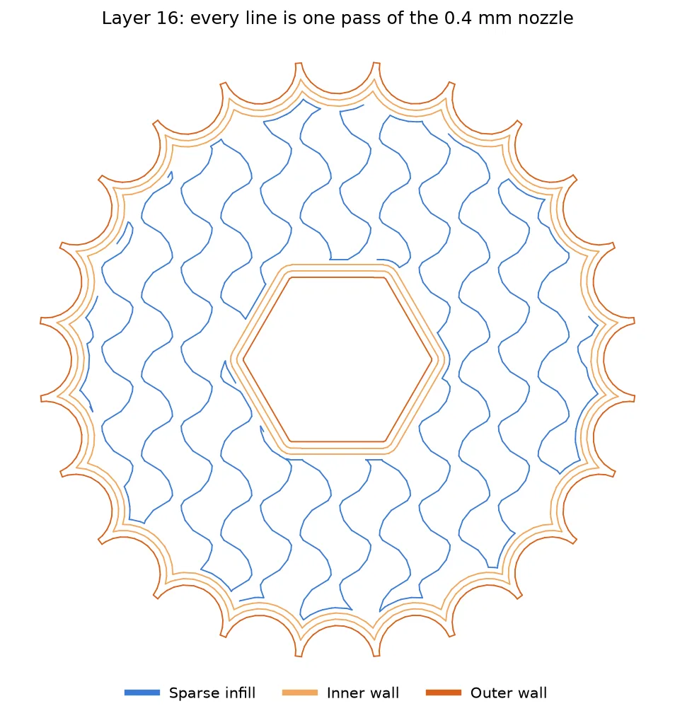
This picture answers questions makers actually ask. Is the wall round the nut thick enough? (Three passes, about 1.3 mm.) Does the infill reach the flutes? (Yes.) You can ask the AI the same questions in words, and it will answer from the file.
Step 4: print, test, adjust
- Print a tolerance test first on a new printer: pegs and holes at 0.1 to 0.5 mm clearance. The one that slides nicely is the number to put in your prompts.
- Change one thing at a time. If the knob's nut is loose, take 0.1 mm off
FITand reprint, nothing else. - Orient for strength. Parts are weakest between layers. A hook printed standing up snaps at the bend; printed on its side, it doesn't.
- Keep the script, not just the STL. Next year you'll want it 5 mm wider.
Check every size against your own parts before printing. The Pi 5 port positions are approximate. None of these parts is designed for load-bearing or safety-critical use.
Need a hand?
Graith Internet builds AI-assisted tools and workflows for small businesses, alongside our Drupal and PHP work. If you want help putting something like this to work in your own business, get in touch.