
What goes in a prompt for a real part
- Units and the sizes that matter. “Millimetres”, every time.
- What it mates with. “An M6 nut, 10 mm across flats”, “a 5 mm D-shaft”, “holes on a 58 × 49 mm rectangle”.
- How it's made. “FDM, 0.4 mm nozzle, PLA, no supports”. This changes the design: clearances, wall thickness, which way up it prints.
- Parameters at the top. So you can change sizes yourself without asking again.
- A self-check. “Print the bounding box”, “print the overlap volume”. The cheapest bug-catcher there is.
Example 1: a pair of meshing gears
Make a pair of meshing spur gears in CadQuery: module 2, 12 and 24 teeth, 20 degree pressure angle, 8 mm thick, bore for a 5 mm D-shaft, 0.1 mm backlash, printed in PLA. Put the gears at the correct centre distance and lighten the big one with holes. Parameters at the top, export STL and STEP, and print the volume where the two gears overlap so we know the teeth don't collide.
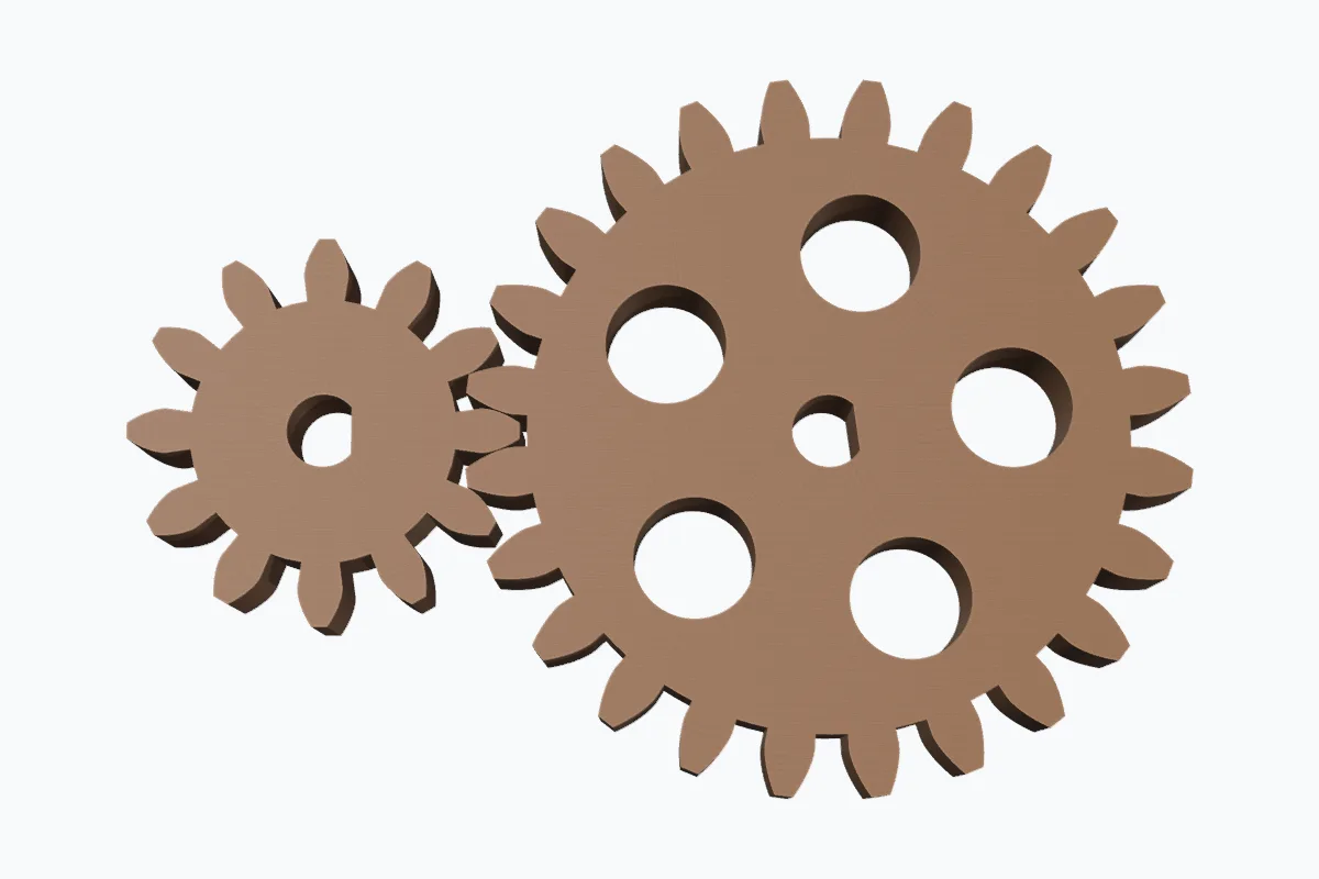
What went wrong first: the first version had thin, pointed teeth with sloping roots. It looked like a gear and would have run badly. Gear teeth follow a curve called an involute, which starts at the “base circle”; on a 12-tooth gear the root sits inside that circle, and the first script didn't draw the straight part of the flank below it. The follow-up that fixed it:
The teeth are too pointed and the roots are wrong. Draw the flank as a radial line from the root circle to the base circle, then the involute from the base circle to the tip, and join neighbouring teeth with a root arc. Re-render from above.
You don't need to know the gear theory to write that follow-up. You need to look at the picture and say what looks wrong. “The teeth look like a star, not like the gears in my gearbox” gets you most of the way.
Example 2: a two-part Raspberry Pi 5 case
Design a two-part case for a Raspberry Pi 5 in CadQuery. Board 85 x 56 mm, M2.5 mounting holes on a 58 x 49 mm rectangle 3.5 mm in from the left and bottom edges. Standoffs 5 mm tall with 2.2 mm pilot holes for self-tapping screws. 2 mm walls, 0.3 mm clearance round the board. Openings for USB-C and the two micro-HDMI ports on one long side, and USB + Ethernet on the short end. Slotted vents in the lid over the CPU. The lid is a push fit with a 0.2 mm gap. Both parts must print without supports.
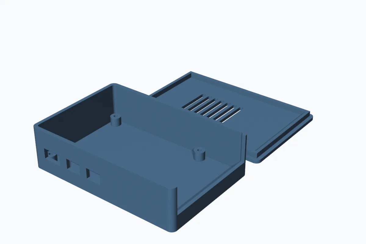
The mounting-hole pattern comes straight from the brief, so it's right. The port positions came from the AI's knowledge of the Pi 5's published mechanical drawing, rounded, with generous openings. That's the kind of number you check: hold a real board against a paper print of the side face, or measure from the board edge. The script says so in its header.
Follow-ups worth trying:
Add a 30 mm fan mount over the vents with M3 holes on a 24 mm square, and a slot in the end wall for the GPIO ribbon cable.
Replace the push-fit lid with four snap-fit clips, 1.2 mm thick, designed for PLA.
Example 3: a thumb knob with a hex nut trap
A knurled thumb knob for an M6 bolt: 40 mm across, 18 mm tall, 24 rounded grip flutes, a hex pocket underneath that traps an M6 nut (10 mm across flats) with 0.2 mm clearance, a 6.5 mm through hole, a domed top with a pointer mark. It must print without supports, nut pocket facing down.
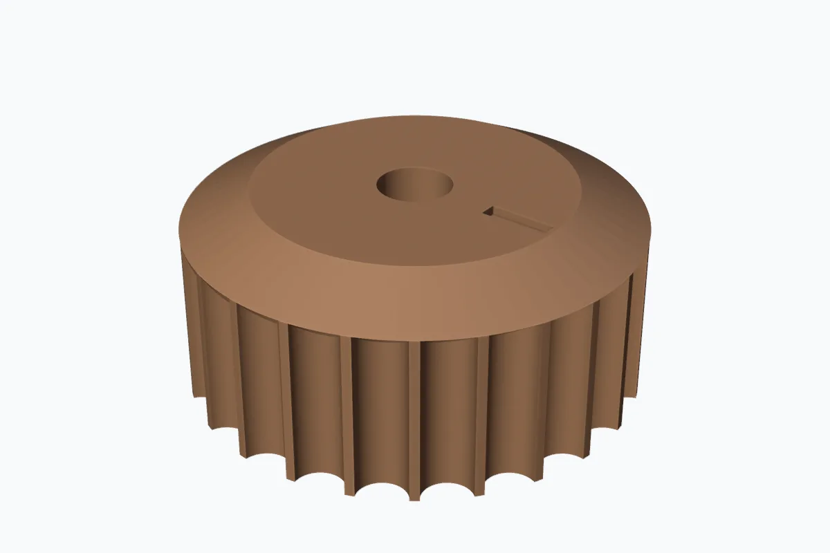
Two fixes were needed. A chamfer on the bottom edge failed because the edge was broken into 48 pieces by the flutes; the AI dropped it rather than fight the kernel. And the pointer mark was first cut below the domed surface, so it barely showed. Looking at the picture caught it; the numbers were all fine.
A detail the AI got right without being asked: the hex is sized across the corners from the across-flats size plus clearance ((10 + 0.4) / cos 30°). That's the classic mistake when people draw nut traps by hand.
A template you can copy
Write a CadQuery script for [what it is]. It fits/attaches to: [the mating part and its measured sizes]. Key sizes (mm): [list them]. Printed on: FDM, 0.4 mm nozzle, [PLA/PETG], no supports, flat face on the bed. Use 0.2 mm clearance per side for sliding fits, 2 mm walls. Put every size as a named parameter at the top. Export STL and STEP, print the bounding box, and render a picture so I can check it.
More prompts for complex things
These all work well as starting points. Expect one or two follow-ups each.
A parametric drawer organiser: tray 300 x 200 x 50 mm split into a grid I set by number of rows and columns, 1.6 mm walls, 3 mm floor, rounded inside corners so it's easy to clean, finger scoops on the front edge.
A print-in-place hinge test: two 30 x 20 x 3 mm leaves joined by a 5-knuckle pin hinge with 0.35 mm clearance between pin and knuckles, printable flat with no supports.
A wall bracket for a 25 mm round broom handle: a C-shaped clip that grips with 0.5 mm interference, a 60 x 40 mm back plate with two countersunk holes for 4 mm wood screws, ribbed so it doesn't snap at the root. Print it on its side so the layers run round the C.
A planetary gearbox, 3:1 to 5:1 selectable by tooth counts: sun, three planets and a ring gear with mounting ears, module 1, 10 mm face width, 0.15 mm backlash. Check the tooth counts are valid for three equally spaced planets and print the ratio.
Convert this OpenSCAD file to CadQuery, keep all the parameters, and tell me any place where the two would produce different shapes. [paste the file]
Where it struggles: real screw threads (use heat-set inserts or nut traps instead), very organic shapes in CAD (use Blender, part 3), and anything where failure hurts someone. Don't print load-bearing, vehicle, climbing or pressure parts from an AI design, or from any design you haven't tested.